
Interested in learning how to program quantum computers? Then check out our Qiskit textbook Introduction to Quantum Computing with Qiskit.
Introduction
In this tutorial we will explore a modified version of the Bucket brigade architecture for QRAM and how to implement them on IBM’s quantum devices.
What is the bucket brigade architecture?
The bucket brigade architecture is a form of QRAM that uses qubits to store classical information. It consists of 3 main parts:
Addressing qubits: These qubits hold the address for the memory cell we wish to read/write
Routing nodes: These are nodes made up of qubits that find the memory cell based upon the states of the addressing qubits
Memory cells: These are made up of qubits that store classical information that we wish to read or write to
Reading a memory cell
Addressing qubits
In order to read a memory cell the user has to encode the address of that memory cell on to the addressing qubits. For example if we want to read from memory cell 01 we encode |01〉 on to the addressing qubits. This would be done by setting q0 to |1〉 using a Pauli X gate and leaving q1 as |0〉
Rule of thumb is there’s N addressing qubits for 2^N memory cells. For example if we have 4 memory cells then we have 2 addressing qubits.
Routing nodes
Once the addressing qubits have been set the states of the routing node qubits will be effected. Whatever qubit in the routing nodes is |1〉will lead to the memory cell that we wish to read.
Reading the memory cell
In order to read the memory cell we apply a toffoli gate. Where the control qubits are the qubits from the routing nodes and the memory cell itself. The target qubit is the readout qubit. If the routing qubit associated with that memory cell is |1〉and the memory cells state is |1〉then the readout qubit will be |1〉. If the memory cells state is |0〉then the readout qubit will be |0〉also.
Writing to a memory cell
In order to write to a memory cell we set the read/write qubit to |1〉with a Pauli X gate. Then the user sets the addressing qubits to the address of the memory cell they wish to write to. This will again affect the routing nodes that will find the memory cell. Then toffoli gates are applied to the memory cells where the control qubits are the read/write qubit and the routing node qubits. The target qubit is again the memory cell. If the read/write qubit is |1〉and the routing qubit associated with that memory cell is |1〉then the memory cells state will be flipped from |0〉to |1〉.
Implementation
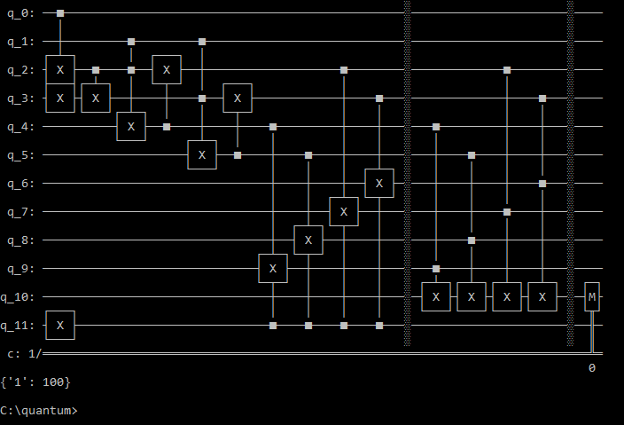
In Qiskit the architecture can be implemented easily with the circuit shown below. Where Q0 and Q1 are addressing qubits (for clarity the implementation only has 4 memory cells and thus only 2 addressing qubits). Q2 to Q5 are part of the routing nodes. Q6 to Q9 are the memory cells. Q10 is the readout qubit that is measured to get the memory cells state and Q11 is the Read/Write qubit.

Circuit diagram of the implemented QRAM circuit
How to run the program
Copy and paste the code below in to a python file
Enter your API token in the IBMQ.enable_account('Insert API token here') part
Save and run
Code
from qiskit import QuantumRegister, ClassicalRegister
from qiskit import QuantumCircuit, execute,IBMQ
from qiskit.tools.monitor import job_monitor

IBMQ.enable_account('ENTER API KEY HERE')
provider = IBMQ.get_provider(hub='ibm-q')

backend = provider.get_backend('ibmq_qasm_simulator')

q = QuantumRegister(12, 'q')
c = ClassicalRegister(1, 'c')

circuit = QuantumCircuit(q,c)

### Addressing ###

#q[0],q[1] -> Memory cell
#  0    0  -> 00
#  0    1  -> 01
#  1    0  -> 10
#  1    1  -> 11

#circuit.x(q[0])
#circuit.x(q[1])

### Routing nodes ####
circuit.cx(q[0],q[2])
circuit.x(q[3])
circuit.cx(q[2],q[3])

circuit.ccx(q[1],q[2],q[4])
circuit.cx(q[4],q[2])

circuit.ccx(q[1],q[3],q[5])
circuit.cx(q[5],q[3])

circuit.x(q[11]) #Write mode (read mode if commented)

### Writing to memory cell ###
circuit.ccx(q[11],q[4],q[9])
circuit.ccx(q[11],q[5],q[8])
circuit.ccx(q[11],q[2],q[7])
circuit.ccx(q[11],q[3],q[6])

circuit.barrier(q)

### Reading memory cell ###
circuit.ccx(q[4],q[9],q[10])
circuit.ccx(q[5],q[8],q[10])
circuit.ccx(q[2],q[7],q[10])
circuit.ccx(q[3],q[6],q[10])

circuit.barrier(q)
circuit.measure(q[10],c[0]) # Measuring readout qubit

circuit.draw(output='mpl', filename='QRAM.png')

job = execute(circuit, backend, shots=100)
job_monitor(job)

counts = job.result().get_counts()

print(circuit)
print(counts)
Output
Output after writing to memory 00 and then reading the same cell