

Interested in learning how to program quantum computers? Then check out our Qiskit textbook Introduction to Quantum Computing with Qiskit.
Updated: 18/11/25
Introduction
In our last tutorial we explored how to correct bit flip errors using the bit flip code. However bit flip errors are not the only potential errors. There is a type of error called a phase flip error.
In this tutorial you will see how a specific type of qubit error called a phase flip can be corrected using a quantum circuit known as the phase flip code.

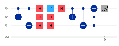
Circuit diagram of the phase flip code
What is a Phase flip error?
A phase flip error is a type of error that effects the phase of the qubit. In essence this error is equivalent to a Z-gate. However as said before it can be corrected using the phase flip code. The phase flip code works identically to the bit flip code in that it first transfers the state of the main qubit to the ancillary qubits using CNOT gates. Next all qubits are put in to superposition using a Hadamard gate.
After this a phase flip error will occur on the main qubit which will effect its phase. After this a Hadamard gate is applied to all qubits again which will take them out of superposition since two Hadamard gates applied leave the state of the qubits unchanged.
However because the main qubits phase was changed it will not be in its previous state but flipped from 1 to 0 or vice versa. Because this has altered the computational state of the qubit we can correct this using CNOT gates and a Toffoli gate where the main qubit is the target and the control qubits are the ancillary qubits.
Check out our tutorial on the Z-gate to learn more about phase flips: https://quantumcomputinguk.org/tutorials/z-gate
See our previous tutorial on correcting bit flip errors: https://quantumcomputinguk.org/tutorials/quantum-error-correction-bit-flip-code-in-qiskit
Implementation
Circuit diagram of bit flip code with simulated error using a Z gate
Step 1: Initialise the quantum and classical registers
The first step is to initialise a 3 qubit register. This is done by the following code:
Next we initialise the 1 bit classical register with the following code:
Step 2: Create the circuit
Next we create quantum circuit using the following code:
Step 3: Apply a CNOT gate to ancillary qubits
Next we will need to transfer the state of the first qubit to the ancillary qubits. This is done using CNOT gates where the ancillary qubits are the targets and the first qubit is the control qubit.
This is done using the following code:
Step 4: Apply a Hadamard gate to all qubits
This puts the qubits in to superposition and is done using the following code:
Step 5: Simulate a Phase flip
To show that the circuit corrects phase flips lets simulate a phase flip error. This can be done by applying a Z-gate to the first qubit:
Step 6: Bring qubits out of superposition by applying Hadamard gates again
This will bring the qubits out of superposition and is done using the following code:
Step 7: Again apply CNOT gates to ancillary qubits
This is done using the following code:
Step 8: Apply a Toffoli gate to the main qubit
This is done using the following code:
Step 9: Measure the qubits
After this we measure the qubits.
This is done with the following code:
Device used
This tutorial uses the Qiskit Aer simulator in order to run the circuit. Note that results from this simulator contain no errors unlike on real quantum devices which are prone to noise.
More information on Qiskit Aer can be found here: https://qiskit.github.io/qiskit-aer/tutorials/1_aersimulator.html
In order to use to a real quantum device follow the steps here: https://quantum.cloud.ibm.com/docs/en/guides/initialize-account
Note: This program requires that you have an API token. To get one sign up to IBM Q Experience and get your token here: https://quantum-computing.ibm.com/account
Code
Output

Output showing the main qubit has been corrected to 0