This tutorial will show you how to implement Grover’s Algorithm on IBMs Quantum Computers in Python with Qiskit
This tutorial will show you how to implement Grover’s Algorithm on IBMs Quantum Computers in Python with Qiskit
This tutorial will introduce the user to the CNOT gate and how to implement it on IBMs quantum computers
The CNOT gate is a mulit-qubit gate that consists of two qubits. The first qubit is known as the control qubit and the second is known as the target qubit. If the control qubit is |1〉then it will flip the targets qubit state from |0〉to |1〉or vice versa.
Proof of Concept is a new exciting tutorial series that will show you how to create quantum applications step by step. In this tutorial we will create a web application that allows users to factor numbers using IBM’s quantum devices. This web application will consist of a backend and frontend.
Updated: 18/11/2025
Interested in learning how to program quantum computers? Then check out our Qiskit textbook Introduction to Quantum Computing with Qiskit.
Superdense coding is a quantum communications protocol that allows a user to send two classical bits by sending only one qubit.

Circuit diagram showing the Superdense coding protocol
First a bell pair consisting of two qubits is prepared where q0 is the senders qubit and q1 is the receivers qubit. In order to create a bell pair a Hadamard gate is applied to q0 followed by a CNOT operation where q0 is the control and q1 is the target.
For more information on bell pairs see our primer on bell states here: https://quantumcomputinguk.org/tutorials/introduction-to-bell-states
Next the sender has to encode the information they want to send on to q0 by applying certain operations to it.
If they want to send 00 then they perform no operation.
If they want to send 01 then they apply a Pauli-Z gate
If they want to send 10 then they apply a Pauli-X gate.
If they want to send 11 then apply a Pauli-Z gate followed by a Pauli-X gate
Next q0 is sent and once received has to be decoded in order to retrieve the information. This is done by applying a CNOT where q0 is the control and q1 is the target. Next a Hadamard gate is applied to q0 and both qubits are measured.
This tutorial uses the Qiskit Aer simulator in order to run the circuit. Note that results from this simulator contain no errors unlike on real quantum devices which are prone to noise.
More information on Qiskit Aer can be found here: https://qiskit.github.io/qiskit-aer/tutorials/1_aersimulator.html
In order to use to a real quantum device follow the steps here: https://quantum.cloud.ibm.com/docs/en/guides/initialize-account
Note: This program requires that you have an API token. To get one sign up to IBM Q Experience and get your token here: https://quantum-computing.ibm.com/account
from qiskit import QuantumCircuit, transpile, ClassicalRegister, QuantumRegister
from qiskit_aer import AerSimulator

def executeCircuit(circuit, backend, shots=1024):

    result = backend.run(circuit,shots=shots).result()
    counts = result.get_counts(circuit)
    print('RESULT: ',counts) # Print result


backend = AerSimulator() # Using local Aer simulator

q = QuantumRegister(2,'q')
c = ClassicalRegister(2,'c')

#################### 00 ###########################
circuit = QuantumCircuit(q,c)
circuit.h(q[0]) # Hadamard gate applied to q0
circuit.cx(q[0],q[1]) # CNOT gate applied
circuit.cx(q[0],q[1])
circuit.h(q[0])
circuit.measure(q,c) # Qubits measured

executeCircuit(circuit, backend, shots=10)

#################### 10 ###########################
circuit = QuantumCircuit(q,c)
circuit.h(q[0])
circuit.cx(q[0],q[1])
circuit.x(q[0]) # X-gate applied
circuit.cx(q[0],q[1])
circuit.h(q[0])
circuit.measure(q,c)

executeCircuit(circuit, backend, shots=10)

#################### 01 ###########################
circuit = QuantumCircuit(q,c)
circuit.h(q[0])
circuit.cx(q[0],q[1])
circuit.z(q[0]) # Z-gate applied to q0
circuit.cx(q[0],q[1])
circuit.h(q[0])
circuit.measure(q,c)

executeCircuit(circuit, backend, shots=10)

#################### 11 ###########################
circuit = QuantumCircuit(q,c)
circuit.h(q[0])
circuit.cx(q[0],q[1])
circuit.z(q[0]) # Z-gate applied
circuit.x(q[0]) # X-gate applied
circuit.cx(q[0],q[1])
circuit.h(q[0])
circuit.measure(q,c)

executeCircuit(circuit, backend, shots=10)
This tutorial will introduce the user to the CNOT gate and how to implement it on IBMs quantum computers
The CNOT gate is a mulit-qubit gate that consists of two qubits. The first qubit is known as the control qubit and the second is known as the target qubit. If the control qubit is |1〉then it will flip the targets qubit state from |0〉to |1〉or vice versa.
Updated: 27/10/25
This tutorial is an excerpt from our textbook Introduction to Quantum Computing with Qiskit.
What is the Hadamard gate?
The Hadamard gate is one of the most important gates in quantum computing. Simply put it puts a qubit in to superposition of states such that if the qubit is |0〉then the state will become:

and if the state is |1〉then the state will become:

This means that when the qubit is measured it will collapse to either |0〉or |1〉with equal probability.
In terms of rotations this corresponds to a rotation of pi radians around the Z-axis followed by pi/2 (90 degrees) around the Y-axis. This means that the pure state will be on the equator of the bloch sphere.
Note that if the state is |0〉then the resulting state will be on the equator of the bloch sphere (known as |+〉) but if it is |1〉then it will be on the opposite side of the equator (known as |−〉).
In quantum computing logic gates are described using matrices. The matrix associated with the Hadamard gate is:

By multiplying the qubits state by the matrix above we can see how the logic gate affects the qubits state. For example if we initialise the qubit to |0〉and apply the Hadamard gate :


Which has mapped:

If we instead initialise the qubit to |1〉and apply a Hadamard gate:

Which has mapped:

Implementation
In Qiskit the Hadamard gate can be demonstrated easily by applying a Hadamard gate to a qubit and then measuring it.

Circuit diagram of the program
Device used
This tutorial uses the Qiskit Aer simulator in order to run the circuit. Note that results from this simulator contain no errors unlike on real quantum devices which are prone to noise.
More information on Qiskit Aer can be found here: https://qiskit.github.io/qiskit-aer/tutorials/1_aersimulator.html
In order to use to a real quantum device follow the steps here: https://quantum.cloud.ibm.com/docs/en/guides/initialize-account
Note: This program requires that you have an API token. To get one sign up to IBM Q Experience and get your token here: https://quantum-computing.ibm.com/account
Source
from qiskit import QuantumCircuit, transpile, ClassicalRegister, QuantumRegister
from qiskit_aer import AerSimulator

backend = AerSimulator() # Using local Aer simulator

q = QuantumRegister(1,'q') # Initialise quantum register
c = ClassicalRegister(1,'c') # Initialise classical register

circuit = QuantumCircuit(q,c) # Initialise circuit
circuit.h(q[0]) # Put Qubit 0 in to superposition using hadamard gate
circuit.measure(q,c) # Measure qubit

circ = transpile(circuit, backend) # Rewrites the circuit to match the backend's basis gates and coupling map

shots = 1024
# Run and get counts
result = backend.run(circ,shots=shots).result()
counts = result.get_counts(circ)

print('RESULT: ',counts) # Print result

Output showing the qubit measurements when measured 1024 times
Interested in learning how to program quantum computers? Then check out our Qiskit textbook Introduction to Quantum Computing with Qiskit.
In our last quantum error correction tutorials we looked at how to correct phase errors and bit flip errors. Each of these errors has a circuit that can be used to correct that particular error but not the other type. For example the bit flip code cannot correct phase errors and phase flip code cannot correct bit flip errors.
For more information on these error correction circuits take a look at our tutorials on them below:
Quantum Error Correction: Bit Flip Code in Qiskit: https://quantumcomputinguk.org/tutorials/quantum-error-correction-bit-flip-code-in-qiskit
Quantum Error Correction: Phase Flip Code in Qiskit: https://quantumcomputinguk.org/tutorials/quantum-error-correction-phase-flip-code-in-qiskit
However there is a specific error correction circuit known as the Shor code which can correct both phase flips as well as bit flip errors. In this tutorial we will explore what the Shor code is and how to implement it in Qiskit.

Circuit Diagram of the Shor Code
The Shor code is a 9 qubit circuit that requires 8 ancillary qubits to correct 1 qubit. For simplification we will call the 1st qubit that we want to correct the main qubit and the ancillary qubits 1 to 8. If you have seen our tutorials on the bit flip and phase flip circuit then the Shor code will look very familiar as it uses the same gates and ordering.
The Shor code works by first taking the computational state of the main qubit and transferring it to the 3rd and 6th qubit. These qubits are used for correcting phase errors. After this these qubits are put in to superposition using a Hadamard gate. Next the states of the main qubit as well as the 3rd, and 6th qubits use CNOT gates to transfer their states to ancillary qubits responsible for correcting bit flips. More specifically the main qubit transfers its state to the 1st and 2nd ancillary qubit. The 3rd transfers it state to the 4th and 5th. The 6th transfer its state to the 7th and 8th qubit.
After this a bit flip or phase flip may occur on the main qubit. in the diagram above this is denoted as E. Next the previous step is repeated. Toffoli gates are then applied to the main qubit as well as the 3rd and 6th qubit where the control qubits are the auxiliary qubits responsible for phase correction.
After this Hadamard gates are applied to the main qubit as well as the 3rd and 6th qubit to bring them out of superposition. Then CNOT gates are applied to the 3rd and 6th qubit where the control qubit is the main qubit. Finally a toffoli gate is applied to the main qubit which is controlled by the 3rd and 6th qubit.

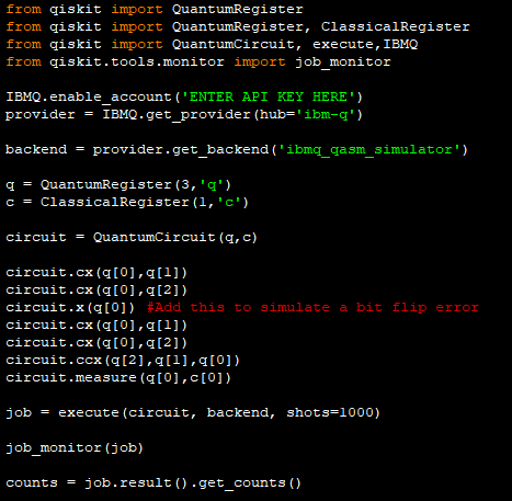
Circuit diagram of Shor code with bit flip and phase flip error
In order to simulate a bit flip and phase error a Pauli-X gate and a Pauli-Z gate will be applied to the main qubit as seen in the circuit diagram above. The Pauli-X gate will simulate a bit flip while the Z gate will simulate a phase flip.
In the code below these simulated errors are implemented using the following:
circuit.x(q[0])#Bit flip error
circuit.z(q[0])#Phase flip error
Copy and paste the code below in to a python file
Enter your API token in the IBMQ.enable_account('Insert API token here') part
Save and run
print('\nShor Code')
print('--------------')

from qiskit import QuantumRegister
from qiskit import ClassicalRegister
from qiskit import QuantumCircuit, execute,IBMQ
from qiskit.tools.monitor import job_monitor

IBMQ.enable_account(‘ENTER API KEY HERE')
provider = IBMQ.get_provider(hub='ibm-q')

backend = provider.get_backend('ibmq_qasm_simulator')

q = QuantumRegister(1,'q')
c = ClassicalRegister(1,'c')

circuit = QuantumCircuit(q,c)

circuit.h(q[0])

####error here############
circuit.x(q[0])#Bit flip error
circuit.z(q[0])#Phase flip error
############################

circuit.h(q[0])

circuit.barrier(q)

circuit.measure(q[0],c[0])

job = execute(circuit, backend, shots=1000)

job_monitor(job)

counts = job.result().get_counts()

print("\n Uncorrected bit flip and phase error")
print("--------------------------------------")
print(counts)

#####Shor code starts here ########
q = QuantumRegister(9,'q')
c = ClassicalRegister(1,'c')

circuit = QuantumCircuit(q,c)

circuit.cx(q[0],q[3])
circuit.cx(q[0],q[6])

circuit.h(q[0])
circuit.h(q[3])
circuit.h(q[6])

circuit.cx(q[0],q[1])
circuit.cx(q[3],q[4])
circuit.cx(q[6],q[7])

circuit.cx(q[0],q[2])
circuit.cx(q[3],q[5])
circuit.cx(q[6],q[8])

circuit.barrier(q)

####error here############
circuit.x(q[0])#Bit flip error
circuit.z(q[0])#Phase flip error
############################

circuit.barrier(q)
circuit.cx(q[0],q[1])
circuit.cx(q[3],q[4])
circuit.cx(q[6],q[7])

circuit.cx(q[0],q[2])
circuit.cx(q[3],q[5])
circuit.cx(q[6],q[8])

circuit.ccx(q[1],q[2],q[0])
circuit.ccx(q[4],q[5],q[3])
circuit.ccx(q[8],q[7],q[6])

circuit.h(q[0])
circuit.h(q[3])
circuit.h(q[6])

circuit.cx(q[0],q[3])
circuit.cx(q[0],q[6])
circuit.ccx(q[6],q[3],q[0])

circuit.barrier(q)

circuit.measure(q[0],c[0])

circuit.draw(output='mpl',filename='shorcode.png') #Draws an image of the circuit

job = execute(circuit, backend, shots=1000)

job_monitor(job)

counts = job.result().get_counts()

print("\nShor code with bit flip and phase error")
print("----------------------------------------")
print(counts)
input()
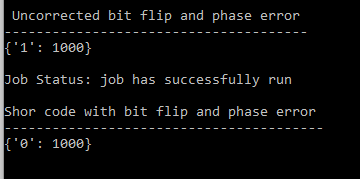
Output of the code. First part shows how a bit flip and phase flip have flipped the value to 1. Second part shows the Shor code has corrected the qubit flip to 0.
Qubits are very fragile and are prone to errors due to decoherence and other quantum noise. However using quantum error correction qubit errors can be corrected.
In this tutorial you will see how a specific type of error called a bit flip error can be corrected using a quantum circuit known as the bit flip code.
Interested in learning how to program quantum computers? Then check out our Qiskit textbook Introduction to Quantum Computing with Qiskit.
This tutorial will introduce you to unitary matrices and how they are used for representing quantum logic gates.
For qubits the computational basis (0 and 1) is represented by two ket vectors:
|0⟩ = 0
|1⟩ = 1
These vectors can be represented as column vectors which are very useful as you will find later:
|1〉=

|0〉=

Matrices are very powerful in quantum computing as they can be used to represent quantum logic gates.
For example the Pauli-X gate:
This is a single qubit gate that flips |0⟩ to |1⟩ and vice versa.
In matrix form it is represented as:

Using this matrix we can use matrix multiplication to see how the Pauli-X gate operates on an input state.
For example if our input state is |1〉:
|1〉=

We then multiply the column vector corresponding to |1〉by the Pauli-X matrix:


Which = |0〉which is correct as the X gate flips |1〉to |0〉and vice versa.
Likewise if our input state is |0〉:
|0〉=

Then again multiply the Pauli-X matrix by the column vector corresponding to |0〉:


Which = |1〉
The Z-gate is a single qubit gate that flips the phase of the qubit such that |0〉is unchanged but |1〉is flipped to -|1〉
We have released a separate tutorial on the Z-gate in detail: https://quantumcomputinguk.org/tutorials/z-gate
The identity matrix for the Z-gate is :

Let’s see how the Z matrix transforms the state of |1〉:
Remember that the column vector for |1〉:

We then multiply the column vector by the Z matrix:


Which = -|1〉
Interested in learning how to program quantum computers? Then check out our Qiskit textbook Introduction to Quantum Computing with Qiskit.
In a previous tutorial we showed how you can get basic information on all quantum devices using backend_overview().
While this function is great to get information on all quantum devices at a glance it is not detailed on specific information such as qubit and gate errors. To get more detailed information on a quantum device (such as configuration and individual qubits and gates) you can use backend_monitor().
Unlike backend_overview() this is for getting information on a specific device so you have to pass the device name in to the function as an argument.
For example to get real time information on the IBMQ Burlngton device you enter the following:
backend_monitor(provider.backends.ibmq_burlington)and for another device like IBMQ Vigo:
backend_monitor(provider.backends.ibmq_vigo)Copy and paste the code below in to a python file
Enter your API token in the IBMQ.enable_account('Insert API token here') part
Save and run
from qiskit import IBMQ from qiskit.tools.monitor import backend_monitor IBMQ.enable_account('ENTER API KEY HERE') # Insert your API token in to here provider = IBMQ.get_provider(hub='ibm-q') backend_monitor(provider.backends.ibmq_burlington) # Function to get all information back about a quantum device print('\nPress any key to close') input() After the code is ran you will be given a list of information about the device including the configuration and specific information on individual qubits and gates.

Screenshot showing the device information for the IBMQ Burlington quantum device.
Interested in learning how to program quantum computers? Then check out our Qiskit textbook Introduction to Quantum Computing with Qiskit.
In this tutorial you will see how to implement the quantum equivalent of a Full Adder on IBMs quantum computers using quantum logic gates.
What is a Full Adder?
A Full Adder is a logic circuit used by classical computers to implement addition on up to 3 bits.

Source: circuitTHEORY
The Full Adder circuit contains 3 inputs: A, B, and Cin (short for Carry in.as it carries in from the previous Full Adder since they can be stringed together)
There are also 2 outputs called Sum and Cout (Short for carry out as it carries out a bit to the Cin of the next adder)
Truth Table


Circuit diagram of a quantum full adder
To implement a Full Adder on a quantum computer we will need 4 qubits (ie 1 for each input and output of the Full Adder).
Q0: Qubit for input A
Q1: Qubit for Input B
Q2: Qubit for Input Cin
Q3: Qubit for Sum
Q4: Qubit for Cout
How it works
For calculating the Sum we simply apply a CNOT gate to Q3 (Sum) from all inputs. This means that if any one of the inputs are 1 then Q3 will be flipped to 1. If all inputs are 0 then Q3 will remain 0.
To calculate Cout (Q4) we apply Toffoli gates with Q4 as the target and the input combinations (Q0,Q1), (Q0,Q2), (Q1,Q2) as the control qubits.
Note: Because of the order of the gates we can never get the Sum and Cout to both equal 1 if only 2 of the inputs are 1.
print('\n Quantum Full Adder')
print('---------------------')

from qiskit import QuantumRegister
from qiskit import ClassicalRegister
from qiskit import QuantumCircuit, execute,IBMQ
from qiskit.tools.monitor import job_monitor

IBMQ.enable_account('INSERT API TOKEN HERE')
provider = IBMQ.get_provider(hub='ibm-q')

######## A ###########################
q = QuantumRegister(5,'q')
c = ClassicalRegister(2,'c')

circuit = QuantumCircuit(q,c)
circuit.x(q[0])
circuit.cx(q[0],q[3])
circuit.cx(q[1],q[3])
circuit.cx(q[2],q[3])
circuit.ccx(q[0],q[1],q[4])
circuit.ccx(q[0],q[2],q[4])
circuit.ccx(q[1],q[2],q[4])

circuit.measure(q[3],c[0])
circuit.measure(q[4],c[1])
########################################
backend = provider.get_backend('ibmq_qasm_simulator')
job = execute(circuit, backend, shots=1)

print('\nExecuting...\n')
print('\nA\n')

job_monitor(job)
counts = job.result().get_counts()
print('RESULT: ',counts,'\n')
######## B ###########################
q = QuantumRegister(5,'q')
c = ClassicalRegister(2,'c')

circuit = QuantumCircuit(q,c)
circuit.x(q[1])
circuit.cx(q[0],q[3])
circuit.cx(q[1],q[3])
circuit.cx(q[2],q[3])
circuit.ccx(q[0],q[1],q[4])
circuit.ccx(q[0],q[2],q[4])
circuit.ccx(q[1],q[2],q[4])

circuit.measure(q[3],c[0])
circuit.measure(q[4],c[1])
######################################
job = execute(circuit, backend, shots=1)
print('\nB\n')

job_monitor(job)
counts = job.result().get_counts()
print('RESULT: ',counts,'\n')
######## A + B ###########################
q = QuantumRegister(5,'q')
c = ClassicalRegister(2,'c')

circuit = QuantumCircuit(q,c)
circuit.x(q[0])
circuit.x(q[1])
circuit.cx(q[0],q[3])
circuit.cx(q[1],q[3])
circuit.cx(q[2],q[3])
circuit.ccx(q[0],q[1],q[4])
circuit.ccx(q[0],q[2],q[4])
circuit.ccx(q[1],q[2],q[4])

circuit.measure(q[3],c[0])
circuit.measure(q[4],c[1])
######################################
job = execute(circuit, backend, shots=1)
print('\nA + B\n')
job_monitor(job)
counts = job.result().get_counts()
print('RESULT: ',counts,'\n')
######## Cin ###########################
q = QuantumRegister(5,'q')
c = ClassicalRegister(2,'c')

circuit = QuantumCircuit(q,c)
circuit.x(q[2])
circuit.cx(q[0],q[3])
circuit.cx(q[1],q[3])
circuit.cx(q[2],q[3])
circuit.ccx(q[0],q[1],q[4])
circuit.ccx(q[0],q[2],q[4])
circuit.ccx(q[1],q[2],q[4])

circuit.measure(q[3],c[0])
circuit.measure(q[4],c[1])
######################################
job = execute(circuit, backend, shots=1)
print('\nCin\n')
job_monitor(job)
counts = job.result().get_counts()
print('RESULT: ',counts,'\n')
######## Cin + A ###########################
q = QuantumRegister(5,'q')
c = ClassicalRegister(2,'c')

circuit = QuantumCircuit(q,c)
circuit.x(q[2])
circuit.x(q[0])
circuit.cx(q[0],q[3])
circuit.cx(q[1],q[3])
circuit.cx(q[2],q[3])
circuit.ccx(q[0],q[1],q[4])
circuit.ccx(q[0],q[2],q[4])
circuit.ccx(q[1],q[2],q[4])

circuit.measure(q[3],c[0])
circuit.measure(q[4],c[1])
######################################
job = execute(circuit, backend, shots=1)
print('\nCin + A\n')
job_monitor(job)
counts = job.result().get_counts()
print('RESULT: ',counts,'\n')
######## Cin + B ###########################
q = QuantumRegister(5,'q')
c = ClassicalRegister(2,'c')

circuit = QuantumCircuit(q,c)
circuit.x(q[2])
circuit.x(q[1])
circuit.cx(q[0],q[3])
circuit.cx(q[1],q[3])
circuit.cx(q[2],q[3])
circuit.ccx(q[0],q[1],q[4])
circuit.ccx(q[0],q[2],q[4])
circuit.ccx(q[1],q[2],q[4])

circuit.measure(q[3],c[0])
circuit.measure(q[4],c[1])
######################################
job = execute(circuit, backend, shots=1)
print('\nCin + B\n')
job_monitor(job)
counts = job.result().get_counts()
print('RESULT: ',counts,'\n')
######## Cin + A + B ###########################
q = QuantumRegister(5,'q')
c = ClassicalRegister(2,'c')
circuit = QuantumCircuit(q,c)

circuit.x(q[2])
circuit.x(q[1])
circuit.x(q[0])
circuit.cx(q[0],q[3])
circuit.cx(q[1],q[3])
circuit.cx(q[2],q[3])
circuit.ccx(q[0],q[1],q[4])
circuit.ccx(q[0],q[2],q[4])
circuit.ccx(q[1],q[2],q[4])

circuit.measure(q[3],c[0])
circuit.measure(q[4],c[1])
######################################
job = execute(circuit, backend, shots=1)
print('\nCin + A + B\n')

job_monitor(job)
counts = job.result().get_counts()

print('RESULT: ',counts,'\n')
print('Press any key to close')
input()
Once you run the code you will get the following output:

Interested in learning how to program quantum computers? Then check out our Qiskit textbook Introduction to Quantum Computing with Qiskit.
IBMs quantum devices all vary whether its in terms of the number of qubits, pending jobs to those devices or whether they are operational at a certain time.
With the backend_overview() function however we can see at a glance information for all those devices which can be very useful if we are deciding what device we should send our program to.
Copy and paste the code below in to a python file
Enter your API token in the IBMQ.enable_account('Insert API token here') part
Save and run
print('\nDevice Monitor') print('----------------') from qiskit import IBMQ from qiskit.tools.monitor import backend_overview IBMQ.enable_account('Insert API token here') # Insert your API token in to here provider = IBMQ.get_provider(hub='ibm-q') backend_overview() # Function to get all information back about each quantum device print('\nPress any key to close') input()After running the code you will see something like the following printed on the screen :

Output showing the status of each quantum device
Want to learn about Quantum Programming? Head over to Quantum Computing UK: https://quantumcomputinguk.org/
If you want to start creating programs for IBMs Quantum Computers then the best way is to use Qiskit.
Qiskit is a framework for quantum computing, allowing you to create programs and then run them either on simulators or on IBMs quantum devices.
Requirements
Python 3.x or above (available here: https://www.python.org/)
Pip: A package management system for Python (included with Python 3.x)
IBM Q Account: This is so you can run your programs on IBM quantum devices. You can sign up for one here: https://quantum-computing.ibm.com
Installation
Install Python 3.x (Make sure Python is added to Path and Pip is checked)
Open Command Prompt and type in: pip install qiskit
Profit!
To Check that qiskit is working download one of our example programs from the code repository here